Solar Water Tank
General ·By Przemek Klosowski
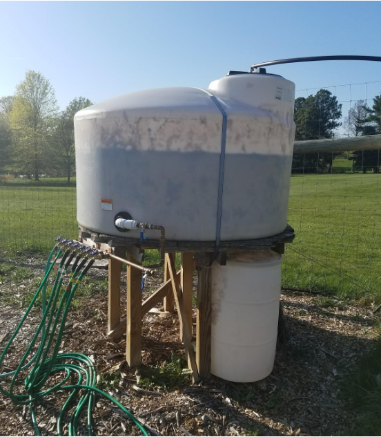
The NIST Employee garden is located in an area without running utility water or electric supply. The gardening requires water, which is available from a lake located about 250 feet downhill. This inspired us to install a water tank that feeds water into several garden hoses distributed near individual gardening plots. Because we lack utility power, we refill that tank with a pump run from a solar-charged battery.
Detailed design
The 500 gallon tank is positioned in the highest spot of the garden, and placed on a 3 ft high platform. This is a compromise between providing enough gravity-fed water flow, and the mechanical and construction details: low structures are more robust and aren’t required to have rails and steps.
The pump specification is determined by the physical layout of the water supply: about 250 feet of ¾” NSF pipe, and about 30 feet of vertical drop between the tank water level and the water table in the lake. The daily water requirements are estimated to be 50 to 100 gallons. We are currently running a sump pump, connected to an inverter fed from a 12 V deep-cycle marine battery. The battery is recharged by a solar panel connected via a solar controller, set to activate the inverter and the pump for one hour a day, after sunset.
System specifications
The pumping volume specifications do not sound like a lot, but in practice we found out that most low-voltage (12 VDC) agricultural-grade diaphragm pumps are not capable of providing reliable operation. We tried several of them, typically rated at 200 gallons per hour and around 100 W of working power. Unfortunately, given the long supply run and 30 feet of water column head pressure those pumps were found unsatisfactory, both in terms of actual pumped volume and long term reliability. We then switched to a centrifugal sump pump using around 250 W at 120 VAC, supplied by a 12 VDC inverter. This gives us an option to run the pump from a portable emergency generator if the battery system is not able to keep up or broken.
The actual inverter load is around 300 W; the 12 V supply draws about 27 A to operate the pump.
The nominal capacity of the battery is around 80 A-hr, so it can handle the hourly operational cycle just fine. Our current setup usually pumps around 60 gallons of water during that cycle.
The solar panel is rated for 100 W, so it is usually sufficient to recharge the battery during an average sunny day. In principle, the system could operate for two hours each day, but it would tax the battery and the re-charging circuit capacity.
Electrical system
The pump supply circuit is housed in three weather-resistant enclosures mounted on a board near the pump location in the lake (the schematic diagram is provided below).
- Battery compartment containing the 80 A-hr deep cycle marine battery and 35 A inline fuse (spare included, taped to the fuse holder).
- Controller enclosure, containing the solar controller, pump relay, terminal blocks and the inverter.
- Disconnect box with fuses (spares included in the box).
The remaining parts are the solar panel, tank water level sensor connected by a buried wire pair, and the sump pump connected by its integral extension cord.
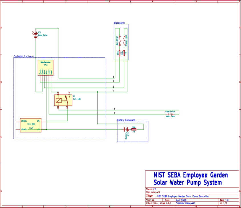
Note that the disconnect de-energizes the solar controller but the load circuit, comprised of the battery, relay and the inverter is separate—the power contact of the relay remains hardwired to the battery. This was done to minimize the length of the high current circuit—it could be rewired if needed.
The solar controller is configured to turn on the load for an hour after the sundown, if the battery is charged above 12 V. The load will cut off if during the load operation the battery voltage drops below 10.7 V, to protect the battery from over-discharge. The float charge is set to 13.7 V.
In actual operation, usually the battery is charged during the day to around 13 V, and one hour of running the pump usually discharges it just under 12.5 V.
Usage Instructions
The physical layout corresponds to the schematic, as seen in the picture. All the voltages are 12 VDC, except the 120 VAC standard IEC output of the inverter, where the sump pump extension cord is plugged in. The disconnect is provided for convenience and as a way of mounting circuit breakers.
The solar controller is a generic unit with an LCD status display. The default view shows battery voltage on the top, and system status on the bottom: left flashing arrow shows that the panel is charging the battery. The battery charge state is depicted by number of horizontal bars within the battery icon. Right arrow and the load symbol should normally be off, as the system is set to turn on the load only for an hour after dark. The left push-button under the display cycles through the settings: float charge voltage, minimum load voltage, disconnect voltage, load-on hours, and battery type.
We should monitor the battery voltage and tank water volume at the beginning and end of the day for a while to get a good sense of the system operation. As this is not automated, it has to be done manually, by recording the battery voltage shown on the default status display of the solar controller, and by reading the water level on the gauge embossed on the side of the tank.
Emergency Generator
When the tank is low on water but the insolation is not sufficient to recharge the battery, or when we expect high water demand exceeding 60 gal/day, we can fill the tank using our gasoline powered emergency generator. The generator is capable of completely filling an empty tank in around 8 to 9 hours.
The procedure for using the generator is as follows:
- Check the generator gas tank and fill with regular gas as needed.
- Place the generator near the solar controller enclosure.
- Turn the generator switch to ON (1).
- Open the valve under the fuel tank (white handle must be vertical).
- Engage the choke.
- Pull starter cord until the engine starts.
- Wait a minute to warm up the engine, place the choke lever in the ‘run’ position.
- Open the solar controller enclosure, unplug the black pump extension cable from the red inverter. The extension cable should be long enough to plug into the generator 120 VAC socket
- After filling the tank to desired level, unplug the pump extension cable from the generator and plug it back into the inverter. Coil up the cable behind the inverter and close the door.
- Close the generator fuel valve (white handle horizontal) and let the engine run out of fuel stored in the carburetor. Turn the generator switch to OFF (0).
- Take the extension cord and plug it into the 120 VAC socket on the generator.